
Normally negative and positive references of the ADC module are VSS and VDD respectively, but VDD is not exactly equal to 5.00V and here we should use the fixed voltage reference as a positive reference of the ADC module. With the fixed voltage reference we get approximately an exact result. The PIC12F1822 MCU has a 10-bit ADC module and a built-in fixed voltage reference (FVR) which makes it a good choice for this application. The ADC module converts analog data into digital data.

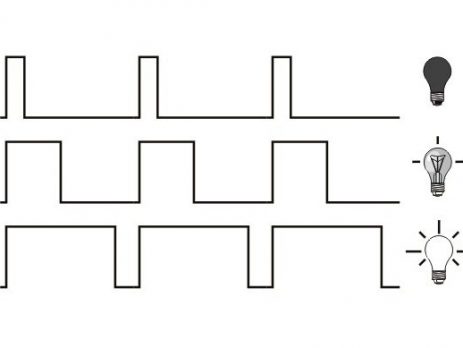
The compiler used in this project is Microchip MPLAB XC8 (MPLAB X IDE with MPLAB XC8 compiler). Temperature data is displayed on 16×2 LCD screen (I2C LCD). This project works also with DFRobot I2C LCD displays. This post shows how to build a simple thermometer using PIC12F1822 microcontroller and LM35 analog temperature sensor. Since the LM35 output varies with dependent to the temperature we need an ADC (Analog-to-Digital Converter) module to measure this voltage. You can use other timers as source for your PWM, but read and make sure if you can or can’t in the datasheet of the device you are using.The LM35 temperature sensor is a three pin device (VCC, OUT and GND) with an output voltage linearly related to Centigrade temperature. Note : Read the datasheet and peripheral library document. Where PWM period = 1/ Frequency (that will be 1/2000 =. So I am going to set the PWM frequency to 2KHz (since using 8MHz as clock source and prescale of 16, getting less than 2KHz is difficult), so the formula according to the datasheet will be (we are going to find PR2) Set the duty cycle (you will be using the functions from pwm.h).Setup the timer (to the frequency/period).Now my task is to make a LED do the heart beat effect (gradually increase/decrease the brightness of an LED using PWM). So in previous tutorial we saw about using a timer. Read this document and you’ll know a lot about PWM : Read the document bellow to find more information. If you use high frequency, then you won’t get the 10 bit resolution. Pulse Width Modulation (PWM) is used everywhere from motors to communication! It uses timer as its foundation to toggle the pins high-low at a defined period (1/frequency) and duty cycle (10 bit resolution – 2 10 = 1024 steps).


 0 kommentar(er)
